

Why 3D CAD Models Lie About Gear Meshing
If you have ever 3D printed or CNC milled a 14-tooth pinion based on standard CAD toolbox parts, assembled it at the textbook center distance, and watched it immediately seize or chew its own tooth roots to plastic dust, you have met the gap between theoretical geometry and physical manufacturing. Standard CAD packages frequently draw simplified tooth outlines that ignore manufacturing clearance, cutter generation trajectories, and thermal backlash.
This gear simulator gives you the unvarnished mathematical and physical picture of external spur gear engagement before you cut metal or spin a motor. Operating a responsive gear simulator online allows you to verify kinematic ratios, check whether your contact ratio stays above the minimum threshold for smooth power delivery, and evaluate the separating forces that your shaft bearings must actually support.
Center Distance, Pitch Circles & Involute Tooth Geometry
Every pair of meshing gears is fundamentally defined by imaginary pitch cylinders rolling against each other without slipping. The radius of these cylinders is the pitch radius, and their tangential velocity at the contact point is identical.
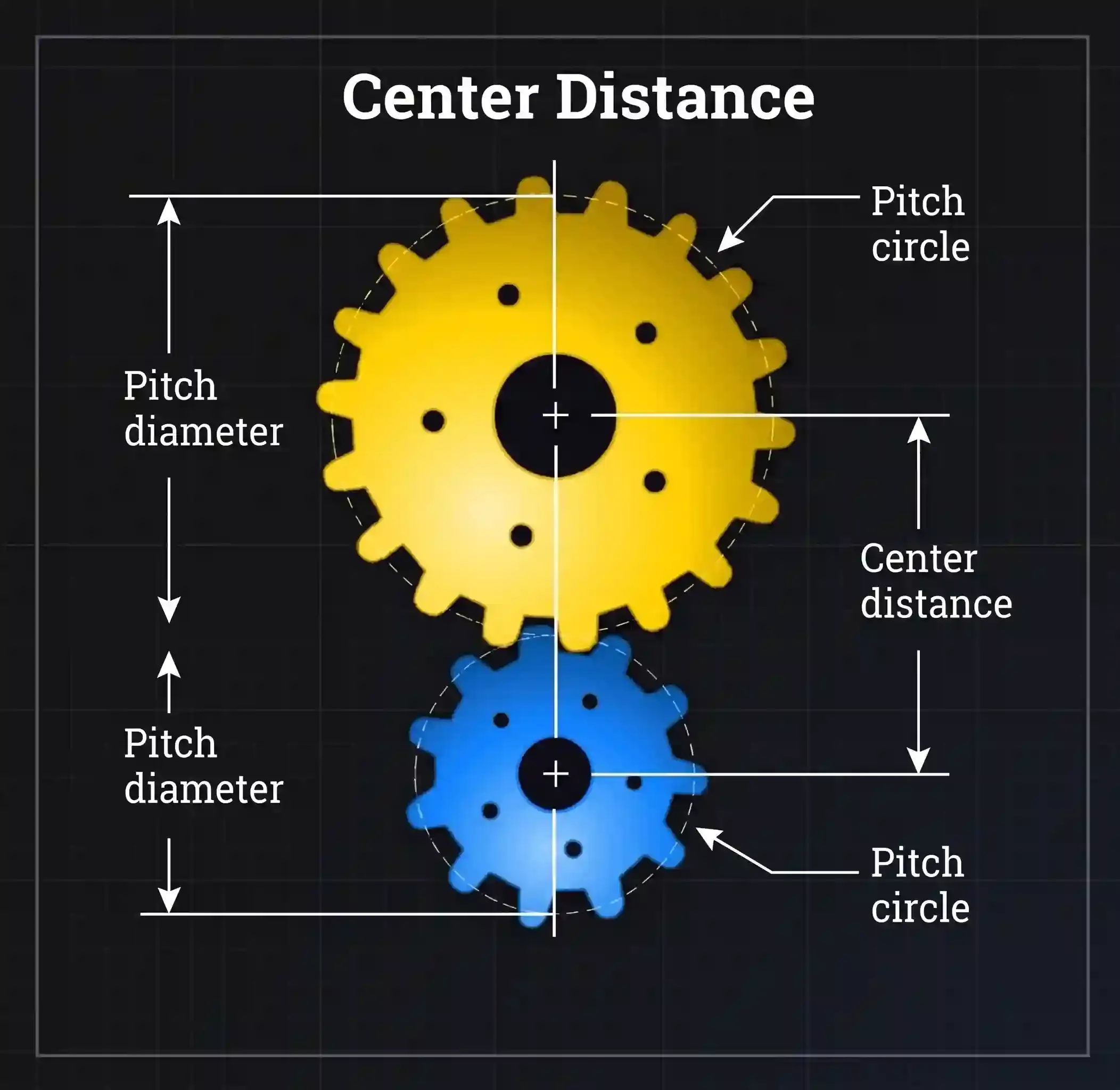
The distance separating the parallel rotational shafts is the operating center distance ($a$). For standard metric spur gears without profile modification, this is simply the average of the two pitch diameters:
Where $m$ is the metric module in millimeters, and $z_1, z_2$ are the tooth counts of the driving pinion and driven gear.
In shop practice, setting center distance to the exact decimal millimeter computed above is a recipe for binding. Real-world machine housings require intentional backlash allowance ($j_t \approx 0.03 \cdot m$ to $0.05 \cdot m$). When gear teeth heat up during continuous operation, tooth flanks expand radially and circumferentially. If there is no clearance between the non-driving flanks, thermal expansion forces the teeth into three-point wedging, destroying lubrication films and overloading bearings.
The Line of Action and Contact Ratio (εα)
What makes the involute curve so brilliant—and why it has dominated mechanical clockwork and automotive drivetrains since Leonhard Euler formalized it in 1765—is that involute gears maintain a strictly constant velocity ratio even if the shaft center distance shifts slightly due to bearing wear or thermal expansion.
During rotation, contact between two teeth occurs exclusively along a straight line known as the line of action (or pressure line), which is tangent to both base circles:
The angle between this line of action and the common pitch tangent is the pressure angle ($\alpha$). Worldwide industrial standards almost universally specify $\alpha = 20^\circ$. Older equipment sometimes uses $14.5^\circ$, while heavy-duty aerospace gearboxes frequently use $25^\circ$ to increase tooth root thickness at the expense of higher bearing loads.
Why You Must Maintain εα ≥ 1.4
The contact ratio ($\epsilon_\alpha$) defines the average number of tooth pairs sharing the transmitted load at any given microsecond. It is calculated by dividing the length of the path of contact ($g_a$) by the base pitch ($p_b$):
If $\epsilon_\alpha$ is less than 1.0, contact is intermittent: one tooth pair disengages before the next pair arrives to take the load, resulting in catastrophic impact hammer and immediate tooth breakage. If $\epsilon_\alpha$ is between 1.0 and 1.2, the handover is harsh and produces loud gear whine. In production machinery, always aim for $\epsilon_\alpha \ge 1.4$ so that at least two teeth share the peak bending stress during handover.
Spur Gear Pairs vs. Planetary Gear Architectures
While this tool models external parallel-shaft spur gear pairs, many high-torque robotics and automotive systems utilize epicyclic gearboxes. When designing high-reduction drivetrains, engineers often weigh single-stage spur reductions against a compact planetary gear simulator setup:
| Architecture | Shaft Arrangement | Typical Ratio Range | Torque Density | Primary Failure Mode |
|---|---|---|---|---|
| Single-Stage External Spur | Parallel offset shafts | 1:1 to 6:1 | Moderate (single contact zone) | Root bending fatigue on pinion |
| Compound Spur Train | Multi-axis offset shafts | 6:1 to 50:1 | Low–Moderate (bulky casing) | Intermediate shaft deflection |
| Epicyclic / Planetary Stage | Coaxial (in-line input/output) | 3:1 to 10:1 per stage | Extremely high (3–4 planets share load) | Planet carrier bearing wear & heat |
A single spur mesh has one point of contact, meaning all torque passes through one tooth root at a time. If you need ratios exceeding 6:1 in a single step with spur gears, the driven gear becomes unwieldy in diameter. That is why high-reduction machinery either steps down across multiple countershafts or switches to a planetary system where three or four planet gears divide the tangential tooth load equally.
Worked Engineering Example: Sizing a 7.5 kW Conveyor Drive
Let us walk through a realistic, messy workshop calculation. Suppose we are designing a reduction drive for an industrial bulk material conveyor powered by a standard 4-pole induction motor:
- Motor Power ($P$): $7.5\text{ kW}$
- Motor Speed ($N_1$): $1440\text{ RPM}$ (accounting for induction slip)
- Target Driven Speed: Approximately $515\text{ RPM}$
- Standard Metric Module ($m$): $2.5\text{ mm}$
- Standard Pressure Angle ($\alpha$): $20^\circ$
- Selected Tooth Counts: Pinion $z_1 = 19$ teeth, Driven Gear $z_2 = 53$ teeth (hunting tooth prime combination)
Step 1: Kinematic Speed & Torque Multiplier
The exact reduction ratio is:
Output shaft rotational speed:
Step 2: Nominal Motor Torque & Output Transmitted Torque
Input torque delivered by the electric motor shaft:
Assuming a realistic enclosed gearbox mechanical efficiency $\eta = 97\%$ (accounting for oil churning and rolling bearing friction):
Step 3: Pitch Diameters & Center Distance
Step 4: Contact Force Vector Breakdown
Tangential force ($F_t$) transmitted along the pitch circle tangent:
Radial separating force ($F_r$) pushing the shafts apart:
Total resultant normal tooth force ($F_n$) acting along the pressure line:
Instructor's Note: That $762.3\text{ N}$ radial force does not disappear. Your shaft pillow block bearings must be sized to support the vector combination of $F_t$ and $F_r$ without shaft deflection exceeding $0.03\text{ mm}$ across the gear face width, or tooth contact will skew heavily toward one edge and cause premature corner spalling. If machining custom housings on a CNC mill, you can verify your toolpath clearance with our G-Code CNC Simulator.
Avoiding the Undercutting Pitfall on Small Pinions
When a pinion is generated using a standard rack hob, if the tooth count is too low, the tip of the hob sweeps into the dedendum flank during generation, cutting away material below the base circle. This is undercutting.
The absolute theoretical minimum tooth count to prevent root undercutting with standard full-depth teeth is:
- At $\alpha = 14.5^\circ$: $z_{\min} = \frac{2}{\sin^2(14.5^\circ)} \approx 32\text{ teeth}$ (very prone to undercutting).
- At $\alpha = 20^\circ$: $z_{\min} = \frac{2}{\sin^2(20^\circ)} \approx 17.1\text{ teeth}$ (in practice, 17 teeth run cleanly).
- At $\alpha = 25^\circ$: $z_{\min} = \frac{2}{\sin^2(25^\circ)} \approx 11.2\text{ teeth}$ (allows ultra-compact pinions).
If your design strictly requires a 12-to-15 tooth pinion at $\alpha = 20^\circ$, you must apply a positive profile shift ($x > 0$). Shifting the hob cutter outward thickens the root flank, eliminating undercutting and increasing bending capacity.
Material Selection & Allowable Contact Stress
A gear pair almost never fails from catastrophic tooth fracture first; it fails from surface fatigue (Hertzian contact pitting) at the pitch line where pure rolling gives way to micro-sliding friction:
| Material Specification | Heat Treatment | Surface Hardness | Allowable Bending Stress $\sigma_{b}$ | Best Suited For |
|---|---|---|---|---|
| AISI 1045 Medium Carbon | Normalized / Through-Hardened | 190–220 HB | 190–220 MPa | Light winches, manual adjustments, low-speed conveyors |
| AISI 4140 Chromium-Moly | Quenched & Tempered (Q&T) | 280–320 HB | 310–350 MPa | Machine tool gearboxes, heavy industrial drive heads |
| AISI 8620 Alloy Steel | Case-Carburized & Ground | 58–62 HRC | 420–480 MPa | Automotive transmissions, racing drivetrains, high shock loads |
| Acetal / Delrin (POM) | Injection Molded / CNC Machined | 85 Rockwell M | 35–45 MPa | Lube-free food processing, office automation, 3D printer drives |
Three Practical Rules of Thumb from 15 Years in the Workshop
- Always Use a "Hunting Tooth" Ratio: In our worked example, we picked $z_1 = 19$ and $z_2 = 53$. Because 19 and 53 share no common factors (they are co-prime), every individual tooth on the pinion touches every tooth on the driven gear before repeating the cycle. This averages out small manufacturing errors and prevents cyclic localized wear patterns.
- Face Width Proportions ($b$): Never make your gear face width arbitrarily wide to compensate for an undersized module. As a solid rule of thumb, keep face width between $8 \cdot m \le b \le 12 \cdot m$. If $b > 15 \cdot m$, shaft torsional windup and angular misalignment will prevent the teeth from touching across their full width, concentrating the entire load on the inner corner.
- Lubrication Determines Life: For pitch line velocities $v < 5\text{ m/s}$, a semi-fluid lithium grease bath is adequate. For $v = 5\text{ to }15\text{ m/s}$, gears require a splash-lubricated oil sump with ISO VG 220 or 320 EP gear oil. Above $15\text{ m/s}$, you must use pressurized oil jet lubrication sprayed directly into the disengaging mesh zone to carry away heat.
Frequently Asked Questions
Why do my gears bind when assembled at theoretical center distance?
Theoretical center distance assumes zero manufacturing tolerance, zero runout, and zero thermal expansion. In real machinery, tooth thickness variations and thermal growth will cause tight teeth to wedge together. Always open up center distance or thin the tooth flanks to provide 0.03–0.05 mm of backlash per millimeter of module.
What is the difference between an online gear simulator and a CAD plugin?
CAD software is designed for solid geometric rendering, but rarely computes dynamic force vectors, operating contact ratios, or mechanical torque efficiencies in real-time. This browser-based simulator provides immediate feedback on kinematic formulas and bearing loads without requiring CAD software licenses or installations.
Can I use this tool to calculate planetary gear train stages?
Yes. Although this visualizer focuses on external 2-gear meshes, the underlying tooth geometry formulas (module, pitch diameter, pressure angle, and base circle) apply directly to sun, planet, and ring gears. You can size the individual sun-planet contact mesh here, then apply planetary speed formulas ($i = 1 + Z_{ring}/Z_{sun}$) for overall carrier reduction.
Why is a 20-degree pressure angle preferred over 14.5 degrees?
A 20° pressure angle provides a significantly thicker, stronger tooth root that resists bending fatigue, raises the undercutting threshold from 32 teeth down to 17 teeth, and improves load-bearing capacity by approximately 15–20% compared to 14.5° gears.