
The Ohm's law equation (V = IR) is the foundational formula of electricity and circuit theory stating that the electrical potential difference or voltage (V, measured in Volts) across a conductor is directly proportional to the electric current (I, measured in Amperes) flowing through it, multiplied by the electrical resistance (R, measured in Ohms, Ω). If you double the voltage, you double the current; if you double the resistance, the current is cut in half.
Interactive Ohm's Law Equation (V = IR & V = IR - e) Calculator
Ohm's Law Equation (V = IR) Definition: What Does the Law State?
When German physicist Georg Simon Ohm published his experimental findings in 1827, electricity was poorly understood. His experimental setup used thermocouples and magnetic needles to measure what we today know as voltage and current.
Formal Ohm's Law Equation V = IR Definition: At a constant temperature and unvarying physical state, the electric current (I) passing through an isotropic conductor is directly proportional to the potential difference (V) across its terminals and inversely proportional to its electrical resistance (R).
The mathematical essence of the Ohm's law equation (v=ir) is expressed algebraically as:
Depending on which two electrical quantities you know, the ohms law equation can be rearranged into three distinct operational forms using the classic Ohm's Law Triangle:
- To find Voltage (V in Volts, V): V = I · R — Multiply the circuit current by the resistance.
- To find Current (I in Amperes, A): I = V / R — Divide the applied voltage by the circuit resistance.
- To find Resistance (R in Ohms, Ω): R = V / I — Divide the measured voltage drop by the flowing current.
Electrical Units & Metric Prefix Conversions for the Ohm's Law Equation
One of the most frequent sources of calculation errors in electronics engineering is unit mismatches. For the Ohm's law equation to produce accurate results, all quantities must either be in standard SI base units (Volts, Amperes, Ohms) or converted using consistent metric prefixes:
| Quantity | SI Base Unit | Common Sub-Units & Multipliers | SI Conversion Factor |
|---|---|---|---|
| Voltage (V) | Volt (V) | Microvolt (μV) Millivolt (mV) Kilovolt (kV) Megavolt (MV) | 1 μV = 10-6 V = 0.000001 V 1 mV = 10-3 V = 0.001 V 1 kV = 103 V = 1,000 V 1 MV = 106 V = 1,000,000 V |
| Current (I) | Ampere (A) | Picoampere (pA) Nanoampere (nA) Microampere (μA) Milliampere (mA) Kiloampere (kA) | 1 pA = 10-12 A 1 nA = 10-9 A 1 μA = 10-6 A = 0.000001 A 1 mA = 10-3 A = 0.001 A 1 kA = 103 A = 1,000 A |
| Resistance (R) | Ohm (Ω) | Milliohm (mΩ) Kilo-ohm (kΩ) Mega-ohm (MΩ) Giga-ohm (GΩ) | 1 mΩ = 10-3 Ω = 0.001 Ω 1 kΩ = 103 Ω = 1,000 Ω 1 MΩ = 106 Ω = 1,000,000 Ω 1 GΩ = 109 Ω = 1,000,000,000 Ω |
| Electric Power (P) | Watt (W) | Microwatt (μW) Milliwatt (mW) Kilowatt (kW) Megawatt (MW) | 1 μW = 10-6 W 1 mW = 10-3 W = 0.001 W 1 kW = 103 W = 1,000 W 1 MW = 106 W = 1,000,000 W |
Golden Shortcut Rules for Fast Mental Calculations
When working on breadboards and PCB schematics, experienced circuit designers use these exact unit-matching shortcuts:
- Rule 1 (mA × kΩ = V): Multiplying current in milliamperes (10-3 A) by resistance in kilo-ohms (103 Ω) gives voltage directly in Volts because 10-3 × 103 = 1. Example: 2.5 mA × 4.8 kΩ = 12 V.
- Rule 2 (μA × MΩ = V): Multiplying microamperes (10-6 A) by mega-ohms (106 Ω) gives Volts directly. Example: 10 μA × 1.5 MΩ = 15 V.
- Rule 3 (V / kΩ = mA): Dividing Volts by kilo-ohms yields current directly in milliamperes. Example: 18 V / 15 kΩ = 1.2 mA.
Ohm's Law Equation Meaning: Developing Physical & Microscopic Intuition
Equations in physics are often memorized as abstract symbols, but understanding the Ohm's law equation meaning becomes effortless when connected to real physical mechanisms and visual models:
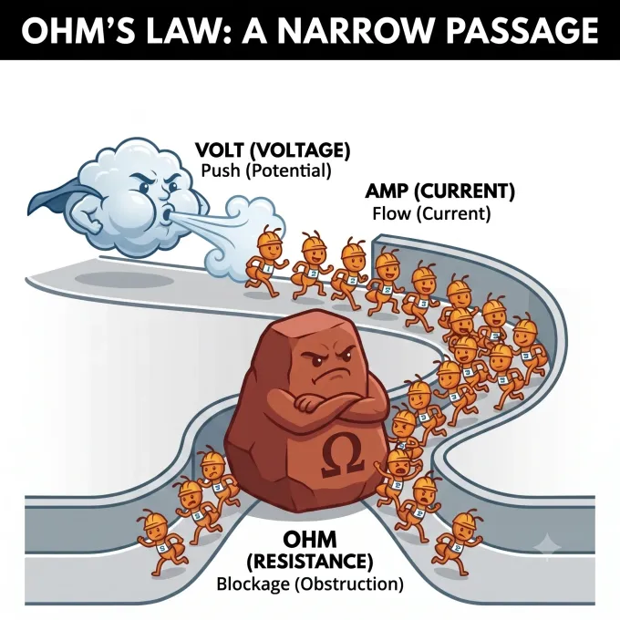
Volt (Voltage) provides the electrostatic push or driving potential from behind, Amp (Current) represents the flow rate of charge carriers marching through the corridor, and Ohm (Resistance) is the physical obstruction constricting the passageway and limiting flow.
1. The Narrow Passage & Visual Obstruction Model
As illustrated in Figure 2 above, think of an electrical conductor as a physical corridor:
- Volt (Voltage — The Driving Push): Voltage is the potential difference created by a power supply. Without voltage, free electrons move in random thermal directions with zero net progression. The voltage "pushes" the charges toward the lower potential.
- Amp (Current — The Traffic Flow): Measured in Amperes (Coulombs per second, 1 A = 1 C/s ≈ 6.242 × 10¹⁸ electrons/s), current is the actual volume rate of electric charges successfully traveling through the corridor.
- Ohm (Resistance — The Obstruction): Resistance acts as a physical blockage or narrowing of the path. If resistance increases, fewer charges can squeeze through per unit time unless the driving voltage push is proportionately increased.
2. The Hydraulic (Water Flow) Analogy
Imagine water moving through an enclosed municipal pipe system:
- Voltage (V) ≈ Water Pressure: Just as water pressure generated by a pump forces water to move, electrical voltage creates an electrostatic field that urges electrons to move through a circuit.
- Current (I) ≈ Volume Flow Rate: Measured in Amperes, current is the actual volume rate of electric charge moving past a given cross-section.
- Resistance (R) ≈ Pipe Restriction or Valve: A narrow, silted, or constricted pipe impedes water flow. Similarly, electrical resistance impedes electron flow through collisions with vibrating atomic lattice ions.
2. Microscopic Electron Drift Velocity
Inside a copper wire at room temperature, free conduction electrons dart around randomly at thermal speeds near 106 m/s. However, because this movement is isotropic (equal in all directions), net current is zero.
When an external voltage creates an electric field across the wire, a gentle macroscopic drift velocity (a fraction of a millimeter per second) is superimposed on top of the thermal chaos. The microscopic differential form of the Ohm's law equation relates current density directly to the electric field:
This fundamental derivation confirms that resistance is not an arbitrary coefficient, but directly stems from material resistivity (ρ), wire length (L), and cross-sectional area (A).
The V = IR - e Equation: Terminal Voltage, EMF & Internal Resistance
In introductory classroom textbooks, voltage sources are often treated as "ideal batteries" that maintain an unyielding potential difference regardless of how much current is drawn. In actual engineering practice, every physical battery, photovoltaic cell, and DC generator possesses an inherent internal resistance (r).
When a load resistor (Rload) is connected across a real battery having an open-circuit Electromotive Force (ℰ or e), current (I) must travel through both the external load and the internal chemical electrolyte:
Why Does Battery Voltage Sag Under Heavy Load?
Applying Kirchhoff's Voltage Law (KVL) around the single-loop circuit gives:
The terminal voltage (Vterminal) that you can actually measure across the battery terminals with a multimeter equals the external voltage drop across the load:
Everyday Engineering Example: When you turn the ignition key in an automobile, the starter motor draws 100 to 200 Amperes. The internal voltage drop I · r inside the battery immediately causes the terminal voltage to sag from 12.6 V down to 10.0 V, which is why your car headlights visibly dim for a split second during engine cranking!
Electric Power & Joule Heating in Ohm's Law Circuits
Whenever current flows against resistance, electrical potential energy is transformed into thermal energy (Joule heating). The electric power (P, measured in Watts, W) dissipated in a resistive circuit is derived directly alongside the Ohm's law equation:
These three algebraic formulations reveal two fundamental engineering design rules:
- Power Line Efficiency (P = I2R): Conductor transmission heat loss scales with the square of current. Halving the current reduces line loss by a factor of 4. This is why power grids step up voltage to 500 kV—higher voltage allows minimal current to transmit the exact same total power (P = VI), eliminating transmission line waste.
- Thermal Sizing (P = V2 / R): When selecting resistors for electronic circuits, always calculate power dissipation. If a 1/4 W (0.25 W) rated carbon resistor is asked to dissipate 0.8 W, it will rapidly overheat, char, and fail open-circuit.
Ohmic vs. Non-Ohmic Conductors: Boundaries & Limitations
Is the Ohm's law equation (v=ir) universally true for all electrical components? No. Ohm's law is an empirical material property (a constitutive relationship), not an inescapable universal law of nature like the conservation of energy.
| Component / Material | Classification | Current-Voltage (I-V) Characteristic | Underlying Physical Reason |
|---|---|---|---|
| Copper & Aluminum Wires | Ohmic | Linear (V ∝ I at constant T) | Carrier density and mean free collision time remain stable under normal current densities. |
| Metal Film Resistors | Ohmic | Strictly linear within rated wattage | Engineered alloy thin-films maintain constant bulk resistivity. |
| Incandescent Tungsten Lamp | Non-Ohmic | Non-linear curve bending toward voltage axis | Filament temperature climbs to 2500 °C; positive temperature coefficient (+PTC) surges resistance by 10× to 15×. |
| Semiconductor Diode (p-n) | Non-Ohmic | Exponential forward curve; zero reverse flow | Conduction requires overcoming the internal depletion barrier potential (Vthreshold ≈ 0.7 V for Silicon). |
| MOSFET & BJT Transistors | Non-Ohmic | Saturated constant-current plateau | Channel carrier flow is modulated by electric gate field rather than passive linear resistance. |
| Gas Discharge / Plasma Arcs | Non-Ohmic | Negative Differential Resistance (NDR) | Thermal ionization generates rapid electron cascades, causing voltage drop to decrease as current rises. |
Step-by-Step Solved Circuit Problem: Applying the Ohm's Law Equation (V = 18V, I = 1.24mA)
Let us solve a complete single-loop DC circuit problem to demonstrate how unit conversion, the Ohm's law equation, and resistor power dissipation are calculated systematically:
Circuit Problem Statement:
Consider the single-loop DC circuit shown in Figure 1. A DC power source supplies a potential difference of V = 18 V across an unknown load resistor (R). An inline ammeter measures a steady circuit current of I = 1.24 mA (0.00124 A).
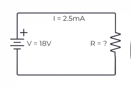
Figure 1: Single-loop DC schematic diagram with DC source and resistor.
Step 1: Convert Given Current (I = 1.24 mA) to Base SI Amperes (A)
In electrical engineering, the Ohm's law equation requires all values to be in standard SI base units. To convert from milliamperes (mA) to base Amperes (A), divide by 1,000 (or multiply by 10-3):
Step 2: Apply the Ohm's Law Equation to Calculate Resistance (R = V / I)
Next, we take the fundamental Ohm's law equation (V = IR) and rearrange it algebraically to isolate resistance (R):
Step 3: Calculate Resistor Heat & Power Dissipation (P = V · I)
To verify thermal dissipation and ensure the resistor will not overheat:
Engineering Wattage Sizing: Since 22.32 mW is well below standard 1/8 W (125 mW) or 1/4 W (250 mW) limits, a standard 0.25 W through-hole or 0805 SMD resistor will operate coolly without heat sinks.
Step 4: Select Commercial Component & Compare Nominal Schematic Benchmark
Because 14.516 kΩ is not an exact production resistor value, we select the nearest standard commercial values from standard resistor series:
- Standard 1% Precision (E96 series): 14.7 kΩ (results in I = 1.22 mA) or 14.3 kΩ (results in I = 1.26 mA).
- Standard 5% Tolerance (E24 series): 15.0 kΩ (results in I = 1.20 mA).
Four Practical Rules of Thumb for the Ohm's Law Equation
- Always Apply a 50% Resistor Wattage Derating: Never run a resistor at 100% of its nominal wattage rating. If your calculated P = I2R is 0.20 W, use at least a 0.5 W resistor to keep surface temperatures below 60 °C and prevent thermal drift.
- Beware of Resistor Temperature Coefficients: Carbon composition resistors drift significantly when heated (+500 ppm/°C). For precision voltage dividers or ADC measurement circuits, always specify metal film resistors with ± 25 ppm/°C stability.
- Test Voltage Drop Under Actual Operating Current: Measuring an open-circuit battery with a high-impedance digital multimeter will show nominal EMF (ℰ) because current is zero (I ≈ 0). Always measure terminal voltage under realistic load to reveal internal resistance.
- Verify Multi-Axis Motion & Actuator Power: When designing mechatronic drive systems, calculate motor coil resistance and back-EMF (e) to ensure your power supply does not sag during rapid acceleration.

Frequently Asked Questions (Ohm's Law Equation FAQ)
What is the Ohm's law equation (V = IR)?
The Ohm's law equation is V = IR, which states that the voltage drop (V) across an electrical conductor is equal to the product of the electric current (I) flowing through it and its electrical resistance (R).
What is V in V = IR?
In the Ohm's law equation V = IR, V stands for Voltage (also termed electrical potential difference or electromotive force). It is measured in Volts (V), representing the electrical energy per unit charge (1 Volt = 1 Joule / Coulomb). Voltage acts as the electrostatic "pressure" that drives free electrons through a conductor.
What is I in V = IR? (What does I stand for or mean?)
In the Ohm's law equation V = IR, I represents Electric Current, measured in Amperes (A) or milliamperes (mA). The symbol I comes from the French phrase intensité de courant (intensity of current). Current is the rate of flow of electric charge through a conductor (1 A = 1 Coulomb per second ≈ 6.242 × 10¹⁸ electrons/s).
What is R in V = IR? (What does R represent or stand for?)
In the Ohm's law equation V = IR, R stands for Electrical Resistance, measured in Ohms (Ω). Resistance is the opposition that a material or component presents to the passage of electric current. It depends on material resistivity (ρ), wire length (L), and cross-sectional area (A) according to R = ρ · (L / A).
What is V = IR and what law is it?
The formula V = IR is known as the Ohm's Law equation, formulated by German physicist Georg Simon Ohm in 1827. It expresses the fundamental linear relationship between voltage (V), current (I), and resistance (R) in DC circuits and linear electrical networks.
Why does V = IR? (Physical and microscopic explanation)
Applying a voltage across a conductor sets up an internal electric field (E). This field exerts a force on conduction electrons, causing them to accelerate until they collide with the vibrating positive ions of the metal lattice. This continuous cycle of acceleration and scattering yields a steady drift velocity, producing current density J = σE. Integrating this over the macroscopic geometry of the wire produces the macroscopic Ohm's law equation: V = IR.
Why does EMF = V + Ir (or why is V = EMF - Ir / V = IR - e)?
Every real battery and generator has internal chemical or winding resistance (r). When current (I) flows, an internal voltage drop (I · r) occurs inside the source. Therefore, the open-circuit Electromotive Force (ℰ or EMF) equals the external terminal voltage (V = IR) plus the internal drop: EMF = V + Ir ⇔ V = EMF - Ir (also written as V = IR - e). This causes battery terminal voltage to sag under heavy load.
What does a resistor do and how is it explained by V = IR?
A resistor is a passive component designed to regulate current flow, provide precise voltage drops, and bias active semiconductor components. According to the Ohm's law equation V = IR, when a current I passes through a resistor of value R, a voltage drop V is produced across its pins, converting excess electrical potential energy into thermal dissipation (Joule heat, P = I2R).
Which formulas are equivalent to the Ohm's law equation V = IR?
Algebraically equivalent variations of the Ohm's law equation V = IR include:
- Current formula: I = V / R (divide voltage by resistance)
- Resistance formula: R = V / I (divide voltage by current)
- Power combinations: P = V · I = I2R = V2 / R
- Microscopic differential form: J = σE = E / ρ
How do you calculate resistance when given V = 18V and I = 1.24mA?
First, convert current into base Amperes: I = 1.24 mA = 0.00124 A. Then apply the Ohm's law equation: R = V / I = 18 V / 0.00124 A = 14,516.13 Ω ≈ 14.52 kΩ. The corresponding power dissipation is P = V · I = 18 V × 0.00124 A = 22.32 mW.